Latest Posts


The different between SD card and MMC is initialization process. The communication protocol of SD card includes SD bus and SPI.
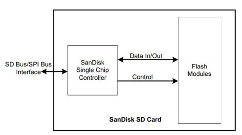
1. Brief introduction bulk SD cards is a memory card base on flash.
The different between SD card and MMC is initialization process.
The communication protocol of SD card includes SD bus and SPI.
SD card implements FLASH operation control, including protocol, safety algorithm, data access, ECC algorithm, defect handing and analysis, power management and clock management, through card intelligent control module.
Communication voltage range:2.0-3.6V; operating voltage range: 2.0-3.6V
Maximum read-write speed:10Mbyte/s
Maximum stack of ten cards(20MHz,Vcc=2.7-3.6V)
 2. Card types
MMC:MultiMedia card,having 7 contacts(pins), there are two modes of operation, MMC mode and SPI mode,and they have different definitions of pins. SPI mode can only be used if the host has SPI interface. MMC only has storage function,while SD card also has encryption function.SD card:Security Digtial card,having 9 contacts(pins), among which two extra pins are data wires,but when using MMC compatible mode, these two extra pins have no use. In addition to storage function, the SD card also has encryption function, but it is not free(so open source linux only contains mmc driver directory),because the original SD Card Alliance (Sony)justinventthis card tostore music (eliminatethe cassette), and use encryption features to prevent copying.
TF card: it is consistent with SD card in software and just smaller than SD in hardware size,So many TF cards on the market are SD shape card ferrule.
SDIO card:this card is nota memory card,We can think of it as a SDIO interface card,such as WIFI(SDIO interface), instead of memory card. just as its name implies, it is input/output card,this card can be used for LAN as well as Bluetooth.
3.SD card protocol
1.x: cards less than 2GB(but it can be simulated to achieve more than 2GB through related software)
2.0: 232GB 4.SD card communication interface
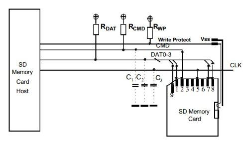
SD card has 9 pins:one VDD, two VSS( GND),CLK,CMD,DATA0-DATA3, 【DATA3 can be used as card detection pin】
SD card can use SD bus interface as well as SPI communication interface; SD bus interface description:

CMD:Command is a bi-directional signal. (Host and card drivers are operating in push pull mode.) 【command and response through this line】
DAT0-3:Data lines are bi-directional signals. (Host and card drivers are operating in push pullmode.) 【real datagoesthrough these lines,data bits can be configured:1~4】
CLK:Clock is a host to cards signal. (CLK operates in push pull mode.)
VDD:VDD is the power supply line for all cards.
VSS[1:2]:VSS are two ground lines.
SPI interface description: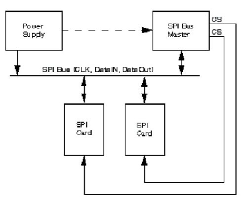
CS:Host to card Chip Select signal. CLK:Host to card clock signal. DataIn:Host to card data signal. DataOut:Card to host data signal.
5. SD card internal structure 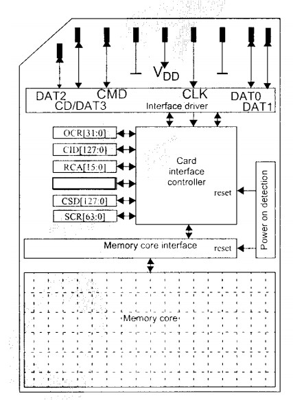
Each sd card has a set of information registers
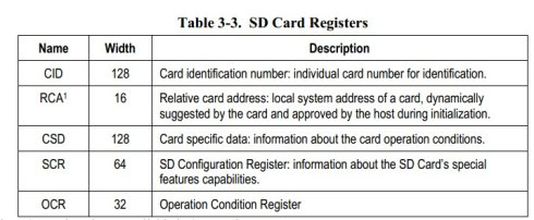 The RCA register is not available in SPI Mode.
OCR:OperationConditionRegisterof card, 32 bit, read-only, 1 bit per 0.1V,whether the process of power on the 31stbit card is completed.
CID: identification register of card, 128 bit, read-only, factory number, serial number for the product,serial number,production date(PD).
SCR: configuration register of card, writable 64bit, whether to use security characteristic(LINUX does not support),and data bit width(1bit or 4bit)
RCA: address register of card: writable 16bit the address for negotiation between SD host and card, kernel will record this address in the code, thecard records it to RCA.
CSD: proprietary data register of card, some are readable and writable, 128bit,card capacity,maximum transmission rate, maximum current for read and write operation, voltage, maximum length of read and write erase block and so on.
The host may reset the cards by switching the power supply off and on again. The card has its own power-ondetection circuitry which puts the card into an idle state after the power-on. The card can also be reset by sendingthe GO_IDLE (CMD0) command.
5. Power-on process of bulk SD cards
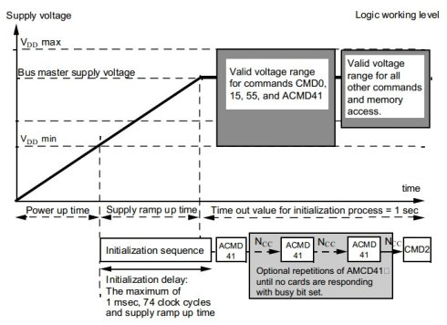
Power-on initialization requires 1ms or 74 CLOCK(SD card's clock,400KHZ). When the voltage of SD card reaches 2.0V,SD card begins to work, the commands supported at this point are very limited(the ACMD41 command is mainly supported,when SD host accesses the operating voltage of the card, the card will readthe operating voltage value programmedin SD Card when it leaves the factory from its OCR and returns the voltage toSD host),when the voltage is adjusted to the required VDD(the working voltage of SD card is between 2.7V and 3.6V,3.3Vis the most common)and the CLK of SD is adjusted from 400KHZ to higher frequency(such as 25MHZ),the card is working perfectly well. Then you can get information about the card manufacturer, capacity and so on. 6. SD card command, response and data transmission format
MMC/SD implements the initialization and data access of card by issuing commands Card addressing is implemented by session address, and addresses are assigned to the card at initialization. The basic operation on SD bus is command/response.
Date transmission through block mode, data block is followed by CRC parity bit, operations include single data block and multiple data block.
Multiple data blocks are more suitable for fast write operations, and multiple data blocks transmission ends when the stop command appears on the CMD line.
Data transmission adopts single or multiple data lines mode that can be set on the host side. BlockwriteoperationsusebusysignalsduringDAT0datalinewriteoperations,regardlessofthenumberofsignallinesusedfortransmission.
Command:ThroughtheCMDLine 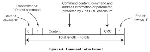 Response:Through the CMD line
Data:Through four data lines 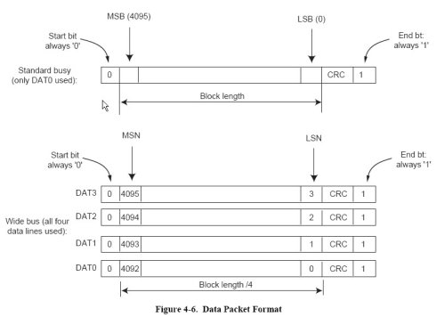
Upto64commandsaresupported: CMD0~CMD63,(CMD57~63is retained)
ACMD: Application Sepcific command:
ACMD41 =cmd55 + cmd41,Combination command, CMD55 is the leading command, reminding the CMD41 which after card is a special command. Type of command Broadcast commands (bc, bcr) – Broadcast commands are sent to all SDcards, and some commands need to be response.
Addressed(point-to-point) commands (ac,adtc)
Addressedcommands are only sent to cards with corresponding addresses, and itneedsto return a response from card.
Broadcast Commands ( bc), no response
The broadcast feature is applicable only if all the CMD linesare connected together in the host. If they are separated then each card will accept it separately on histurn. Broadcast Commands with Response (bcr )
response from all cards simultaneously. Since there is noOpen Drain mode in SD Card, this type of command is used only if all the CMD lines are separated.The command will be accepted and responded to by every card separately. Addressed (point-to-point) Commands (ac )
no data transfer on DAT. Addressed (point-to-point) Data Transfer Commands (adtc)
data transfer on DAT.
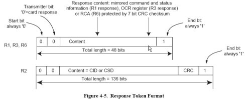
Response:R1 (standard response):response length 48 bitR1bis identical to R1 with an optionalbusy signaltransmitted on the data lineR2 (CID, CSD register):response length 136 bits.The content of the CID register is sent as a response toCMD2 and CMD10. The content of the CSD register is sentas a response toCMD9.R3 (OCR register):response length 48 bits.The contents of the OCR register are sent as a response toACMD41.R4~R5:responses are not supported.R6:(Published RCA response): code length 48-bit, response toCMD3
7. Status of SD card 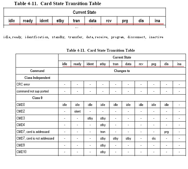 8. Operation mode of SDcard
There are also two types of operations for card: Card Recognition Mode– – When the host looks upnew cardson the bus after reset, it is in card recognition mode. After resetting, SDcard will remain in this mode until the SEND_RCA command (CMD3) isreceived. Data transmission mode – – Once the card’s REC is released, it will enter the data transmission mode. Once the host recognizes all the cards on the bus, it will enter the data transmission mode. Card Recognition Mode 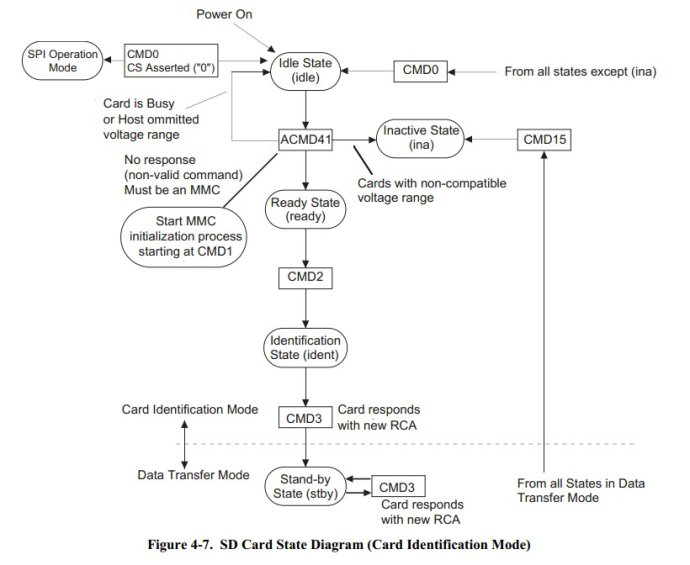
GO_IDLE_STATE (CMD0) is a software reset command that sets each SD card to the Idle state.The card in the Inactive state is not affected by this command.Whenthe host is powered on, all SD cards enter the Idle state, including cards in the Inactive state.Bus transmission cannot start until at least 74 clock cycles. After power-on or CMD0 (reset), all SD card command lines are in input mode, waiting for the start of the next command.The card is initialized by
a default relative card address RCA (RCA = 0x0000) and default drive register settings (minimum speed, maximum drive current).
The SD physical specification standard requires that all SD cards can communicate with the host through any voltage between the minimum and maximum supply voltages. However, the minimum and maximum voltage values for data transmission are defined in the operating condition register OCR,may not cover all voltage ranges.
The SD card host hopes to obtain the appropriate voltage value or pop-up card by reading the OCR of card.
The host starts the card recognition process at the recognition clock rate fOD. SD card’s CMD line output driver is push-pull driver. After the bus is activated, the host requests card to send their valid operating conditions (ACMD41 preceding with APP_CMD-CMD55 with RCA = 0x0000). The responds of ACMD41 command isthe operating condition register of card. The same command will be sent to all cards in the system. Incompatible cards will enter the Inactive state. Then thehost sends the command ALL_SEND_CID (CMD2) to each card to obtain the unique identification CID number of each card. The unidentified cardssend the CID number through the CMD line in response. When the card sends the CID number, it enters the Identification State. Thereafter, the host sends CMD3 (SEND_RELATIVE_ADDR) to request card to issue a new relative card addressRCA, which is shorter than CID and is used to addressingcard in future data transmission mode. Once RCA is obtained, the card state becomes Stand-by state. At this point, if the host requests the card for other RCA numbers, it can send another SEND_RELATIVE_ADDR command to the card, requesting a new RCA tobe issued, and the final RCA issued is the actual RCA used. The host repeats the identification process for each card in the system. After all SDcards are initialized, the system will begin to initialize the MMC (if any), using CMD2 and CMD3of the MMC.
Data transmission mode 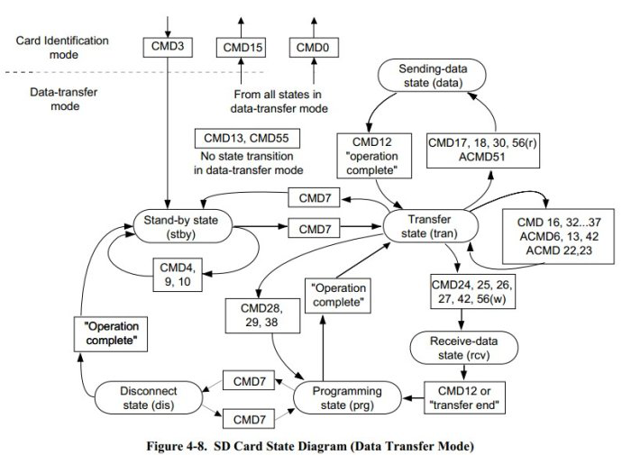
The FPP clock rate must be kept at fOD until the host knows the allcontents of CSD registers,because the operating frequency of some cards is limited. The host sends SEND_CSD (CMD9) to obtain card definition data (Card Specific Data, CSD register), such as block size, card storage capacity, maximum clock rate, etc.
CMD7 is used to select a card and put it inthe Transfer State. Only one card can be in theTransfer State at any time. If a card is already in the Transfer state, its connection to the host will be released and returned to the Stand-by state.
When CMD7 is sent as the reserved relative address “0x0000”, all cards will return to the Stand-by state. This can be used to identify new cards without resetting other registered cards. In this state, a card with RCA address does not respond to the identification command (ACMD41, CMD2, CMD3).
Note: When card receives a CMD7 with a mismatched RCA, cardwill be unchecked. When theCMD line is used publicly, the other cards are automatically unchecked when one card is selected.
Therefore, in SDcard system, the host has the following functions:
After the initialization is completed, when theCMD line is used publicly, it is automatically completed to uncheck the card.
If you use a separate CMD line, you need to pay attention to the operation of uncheck the card.
All data communications between the host and the selected SD cardare point-to-point. All addressedcommands need to be responded to.
The relationship between different data transmission modesasshown in Figure 4-8, using the following steps:
All read data commands canbe abortedby stop command (CMD12)at any time. Data transmission willbe aborted and card will return to the Transfer State. Read commands include:block read command (CMD17), multi-block read command (CMD18), send read protection (CMD30), send SCR (ACMD51), and the general command of read mode (CMD56).。
All write data commands can be abortedby stop command (CMD12) at any time. Writecommands must stop before the card command CMD7 isunchecked. Write commands are: block write commands (CMD24 and CMD25), write CID (CMD26), write CSD (CMD27), lock/unlockCommand (CMD42) and Write Mode Command (CMD56).
Once the data transfer is completed, the card will withdraw fromthe data write state and enter Programming State or Transfer State.
If a block write operation stops and the last block length and CRC are valid, the data can be programmed.
Cards may provide block write buffers. This means that when the previous block data is manipulated, the next block data can be transmitted to the card. If all card write buffers are full, DAT0 will keep alow level (BUSY) as long as card is in Programming State.
There is no buffer for writing CSD, CID, write protection and erase. This means that when card is busy with these commands, it no longer receives other data transmission commands. DAT0 maintains a low level and is in Programming State when card is busy. In fact, if the CMD and DAT0 lines are separated, and the busy DAT0 lines occupied by the host are separated from other DAT0 lines, then the host can access other cards when the card is busy.
When card is programmed, parameter setting commands are prohibited. The parameter setting commands include: setting block length (CMD16), erasing block start (CMD32) and erasing block end (CMD33).
Cards are not allowed to read commands while operating.
Using CMD7 instruction to transfer another card from Stand-by state to Transfer state does not stop erasing and programming operations. The card will switch Disconnect stateand release the DAT line.
When using CMD7 instructions, you can uncheck the card in Disconnect state. The card will enter the Programming state and reactivate the busy indication.
Using CMD0 or CMD15 reset cards will abort all hang and active programming operations. This may destroy the data content on the card, requiring the host to ensure that such operations are avoided. 9. Whether SD Card Chooses Wide Bus
Wide Bus (4-bit Bus Width) operation mode is selected or not selected by ACMD6. The default bus width is 1 bit after power-on or the GO_IDLE (CMD0) command. The ACMD6 command is only valid in “tran state”, that is, the bus width can only be changed after the card is selected. 10. SD card Read Data Format
The DAT bus is at a high level when there is no data transmission. Atransmission block contains a start bit (LOW), followed by a continuous stream of data. Data flow containsvalid data (including error correction bits if ECC is used). The data flow ends with an end bit (HIGH). Data transmission and clock signal are synchronized.
Valid data transmitted by blocks contains CRC, which produces standard CCITT polynomials and uses shortened BCH codes,d = 4,andthe maximum length of valid data is 2048 bytes.CRC calculates each DAT line singly and attaches it to each data block.In wide bus mode operation (DAT0-DAT3), 16-bit CRC are calculates each DAT separately.
Data BlockRead:The basic unit of transmission is the data block. The maximum size is defined in CSD (READ_BL_LEN).It can also be transmittedif the start and end addresses are completely contained in a smaller block contained in a physical data block(such as the READ_BL_LEN definition).CRC is attached at the end of each data block to ensure the integrity of data transmission. CMD17 (READ_SINGLE_BLOCK) starts a block read operation and then enters the Transfer state after the transmission is completed. CMD18 (READ_MULTIPLE_BLOCK) starts continuous block transmission until the command stops. The execution of the stop command will be delayed and the data transmission will stop after the last bit of the stop command has been sent.If the host uses the block whose accumulated length is not block alignment,At the beginning of the first misaligned block, the card will find theerror of misaligned block, and set the ADDRESS_ERR error in the status register, stoppingthe transmission and wait for the stop command (in the Data state).
11. SD Card Write Data Format
The data write transfer format is similar to the read format. For block-based write data transmission, CRC check bits are attached to each block.After each data line of the card receives the data, the card executes CRC before writing operation.
Data block write
Data block writing (CMD24-27, 42, 56 (W)), one or more data blocks are sent from the host to the card, and the host adds CRC after each data block. Data block length WRITE_BL_LEN (512B). If CRC fails, the card will indicate an error on the DAT data line. The transmitted data will be discarded, and subsequent transmissiondata blocks (in multiple data block write mode) will also be ignored.
Writing commands in multiple data blocks is faster than writing commands in successive single data blocks. Partial block writing is not allowed (less than 512B).
Writing aborts when the host attempts to write data to the protected area. In this case, the card sets the WP_VIOLATION bit in the status register, ignoringall subsequentdata transmission, and waits for the stop command in the Receive-data state.
There is no need to set block length when programming CID and CSD registers, and the data transmitted is also protected by CRC. If a part of CSD or CID register is stored in ROM, the immutable part must be consistent with the corresponding part of the receive buffer. If match fails, the card will report an error without changing any register contents.
After receiving a data block and completing CRC, the card will start writing. If the write buffer is full and cannot receive a new data from a new WRITE_BLOCK command, the DAT0 line keeps alowlevel. At any time, the host can get the status of the card through the SEND_STATUS (CMD13) command. The status bit READY_FOR_DATA indicates whether the card can receive new data or write operations are still in progress. The host uncheckscard through CMD7 (select another card). This operation candisconnectthe state programming of the card and release the DAT line without interrupting writing. When the card isunchecked, if the programming is still in progress and the write buffer is not available, the busy signal will be reactivated by dropping down the DAT to a low level. In fact, the host can write multiple cards simultaneously through interleaving, and the interleaving process can be implemented by accessing other cards when the card is busy.
Pre-erase settings take precedence overmultiple data blocks write operations
Setting up thepre-erase of multiple write data blocks (ACMD23) can make subsequent write operations of multiple data blocks faster than the same operation without Pre-execution of ACMD23. The host can set up multiple data blocks to be sent in subsequent write operationsthrough this command. If the write operation is aborted when all data blocks are sent to card (using stop transfer command), the content of the remaining write data blocks (referring to the data blocks to be written to the new content) will become uncertain (perhaps erased or original data). If the host sends more data than the number of data blocks defined in ACMD23, the card will erase the blocks one by one (when new data is received). When the multi-block write operation is completed, the value will be reset to the default value of 1. It is recommended to use this command before the CMD25 command to speed up the writing. If you want to pre-erase the host, you need to send ACMD23 before writing the command.If the ACMD23 command is not sent, the set number of pre-erases will be automatically cleared when other instructions are executed.
Sending the numberof writedata blocks
The systemmanagesdata buffers through thepipelinescheme,sometimes errors occur in the process of writing multiple data blocks, which makes it impossible to confirm which data block is the last successfully written data block.The card can take the number of well-written blocks as a response to the command ACMD22.
Erase
Erasingmultiple write blocks at the same time can improve data throughput. The recognition of write block is realized by ERASE_WR_BLK_START (CMD32) and ERASE_WR_BLK_END (CMD33).
The host must operate in strict accordance with the following order of command: ERASE_WR_BLK_START, RASE_WR_BLK_END, and ERASE (CMD38).
If the eraseinstructions (CMD38) or address setting instructions (CMD32, 33) are not received in sequence, the card will set ERASE_SEQ_ERROR bits in the status register and reset the entire sequence.
If an unordered command is received (except SEND_STATUS), the card will set ERASE_RESET status bit in the status register, resettingthe erase order, and execute the final command.
If the erase scope includes write-protected sectors, it will not be erased, and theerase command only erases unprotected sectors.
The WP_ERASE_SKIP bit of the status register will be set
The address in the address setting command is a block writeaddress in bytes. The card ignores all LSBssmaller than WRITE_BLK_LEN (CSD).
As mentioned above, the card indicates that the erase operation is in progress by keep The actual erase operation may take a long time, and the host can uncheck the card by CMD7 or disconnect the card
D7or disconnect the card
The data after erasing operation on the card is “0” or “1”, which is determined by the card manufacturer. DATA_STAT_AFTER_ERASE (bit55) of SCR registers defines it as “0” or “1”.


Leave a comment