Latest Posts


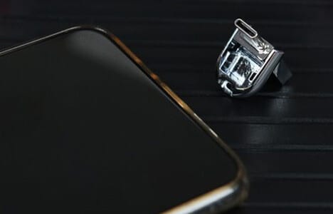
OTG Description
OTG is the technology developed in recent years, and is applied on the connection between various devices or mobile devices
OTG is the abbreviation of On-The-Go. It is a technology that was developed in recent years. It was launched by the USB Implementers Forum on December 18, 2001, and is mainly used in the connection between various devices or mobile devices for data exchange.
Especially on Pads, mobile phones, and other consumer devices. It can help solve the inconvenience of exchanging data among devices with different connector standard, such as digital cameras, video cameras, printers and other equipment, since there are 7 types of memory card standard. It start to become popular in the market since about 2014.
Content
1.Produce Background 2. Effect 3. Classification 4. Principles Design Principles Related Principles 5. Communication Protocol 6. Development
Development
Produce background
The development of USB technology enables PCs and peripheral devices to connect devices with various data transfer speeds together in a simple way and at moderate manufacturing costs. The applications we mentioned above are all connected to the PC through USB, and data exchange is carried out under the control of PC.
However, when using this convenient exchange method, the devices cannot use the USB port to operate on each other without a PC, because no other device can act as a host.
Effect
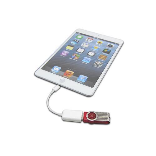
OTG technology can realize data transmission between devices without a Host. For example, the digital camera can directly connect to the printer through USB port with OTG technology, and print out photos immediately. You can also send data stored in digital camera to mobile hard disk with the USB interface through OTG. In this way you no longer need to bring expensive memory cards or carry a portable computer for field operations.
Through OTG technology, you can enrich the functions of smart terminal USB interface accessories, such as extending remote control accessories like turning mobile phones and tablets into universal remote controls.
Classification
According to the USB interface protocol, OTG can be divided into 3 categories:
USB2.0 OTG
Micro 5PIN OTG: common Android phone OTG interface
Mini 5PIN OTG: common Android tablet OTG interface
Micro USB3.0 OTG: OTG interface on Samsung Note3, Galaxy S5 and other Android phones launched before 2016
Type C OTG: OTG interfaces on Samsung Note 8, Galaxy S8, LeTV, Huawei and other Android phones launched after 2016
Principle
Design principle
With the popularization of consumer products such as PADs, mobile phones, digital cameras, printers, etc., high-speed data transmission technology between these devices and computers, or between devices and devices, has attracted more and more attention. IEEE1394 and USB are the two main criteria for such transmissions.
Both standards provide plug-and-play and hot-swap functions, both can provide power to outside devices, and both support multiple device connection. Among them, IEEE1394 supports higher data transmission speed, but is relatively complex and expensive, and is mainly used for AV products that require high-speed communication. The initial USB standard is mainly for low-speed data transmission applications, of which USB1.1 supports 1.5Mbps and 12Mbps transmission rate. It is widely used in PC peripherals with low transmission rate requirements, such as keyboards, mice, etc. The introduction of the USB2.0 standard allows the transmission speed of USB to reach 480Mbps. The introduction of USB OTG technology can realize data transmission between devices without a host. For example: a digital camera can be directly connected to a printer and print photos, thus expanding the application range of USB technology.
Relevant principle
We all know that since the launch of the USB transmission protocol in 1996, it has quickly become popular among all computer peripherals and digital devices with its advantage. We all know that USB devices are divided into HOST (master device) and SLAVE (slave device). Data transmission can only be accomplished when HOST and SLAVE are connected. The OTG device is our “EX”, it can act as both the HOST and the SLAVE.
Communication Protocol
Except from fully compatible with the USB2.0 stand, USB OTG standard has added power management (power saving) functions. It allow device to operate as both host and peripheral (dual-purpose OTG). The dual-purpose OTG device fully complies with the USB2.0 standard, and can provide a certain host detection capability. It supports host notification protocol (HNP) and dialog request protocol (SRP). In OTG, the initial host device is called the A device and the peripheral is called the B device. The initial role can be determined by the way in which cables are connected. Figure 1 shows the way of using the fifth ID pin to determine the default host. Dual-purpose devices use the new mini-AB receptacle, which adds a fifth pin (ID) to the mini-A plug, mini-B plug, and mini-AB receptacle to identify the different cable endpoints. The ID pin in mini-A plug is grounded while the ID pin in mini-B plug is floated. When the OTG device detects a grounded ID pin, it will set the device as the A device (host) by default. When it detects a floating ID pin, it will consider the device as the B device (peripheral). Once the system is connected, the role of the OTG can still be changed. The host and peripherals use the new HNP. A device acts as the default host and provides VBUS power, reset bus when detect device connection, and enumerated and configured the B device. The second new protocol that the OTG standard adds to USB is called the Session Request Protocol (SRP). SRP allows the B device to request A device to turn on VBUS power and initiate a conversation. An OTG session can be determined by how long the A device supplies VBUS power (note: the A device always supplies VBUS power, even when set as a peripheral). You can also end a session by using the A device to turn off the VBUS power to save power consumption, which is very important in battery-powered products. For example, when two cellular phones exchange information with each other through the connection, one of them is connected to the mini-A end that consumes electricity, which is the A device and is the host by default. The other is the B device, which defaults to the peripheral. When USB communication is not required, the A device can turn off the VBUS line, and then the B device will detect this state and enter a low power consumption mode.
Host Negotiation Protocol
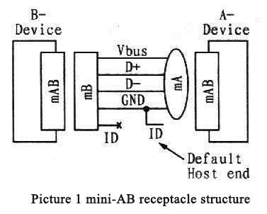
Figure 1 mini-AB receptacle structure
In the USB standard, the host adopts a type A interface, which is called a type A device (A Device); the peripheral adopts a type B interface, which is called a type B device (B Device). A DRD can be used as both a host and a peripheral. So, when 2 DRDs are connected, which one is the host and why should it be the host? In order to solve these two problems, a new protocol, Host Negotiation Protocol (HNP), is proposed in OTG. A new interface is also defined in OTG — mini-AB receptacle, mini-A plug and mini-B plug. 1 pin, ID pin, has been added to the mini-AB receptacle, mini-A plug and mini-B plug, as shown in Figure 1. Host Negotiation Protocol (HNP)
In a mini-A plug, the ID pin touches ground, and in a mini-B plug, the ID pin is floating. In OTG, if the ID pin of the device touches ground (that is, the device connected to the mini-A plug, such as the device on the right side of Figure 1), the device will be signed as the host by default, otherwise it is the peripheral. At the same time, during the connection and usage process of the device, the host and peripheral functions are allowed to be swapped through the host negotiated protocol. For example, assume that the B Device on the left of Figure 1 is a handheld PDA, and the A Device on the right is a printer. Due to the way they connect, the printer is initialized as the host. However, the driver of the printer exists in the PDA. Thus, the PDA needs to be set as the host and the printer should be set as peripheral. This change can be easily realized through HNP, you no longer have to unplug the cable, change the direction of the plug and reconnect the printer and PDA.
session request protocol
OTG transceivers are generally used in embedded devices. These devices are generally powered by batteries and have strict power consumption requirements. To save power, in the OTG standard, A devices are allowed to suspend the power bus when the power bus is not in use. When a B device need to work, it must find a way to notify A device to supply power to the power bus. In order to realize this function, the Session Request Protocol (SRP) is proposed in OTG. In OTG, a session is defined as the time that a A device effectively supplies power to the power bus VBUS. It should be noted that the power is always provided by the A device in OTG (the DRD connected to the mini-A plug). Due to the host negotiation protocol, A devices can also be used as peripherals, but still provides power. When a A device suspends VBUS, B device goes to sleep mode. When the B device needs to work again, it can request the A device to supply power to the power bus by sending a pulse signal (Data-linePulsing) to the data cable or a pulse signal (VBUSPulsing) to the power bus. The OTG requires that both DRD devices and all ordinary B devices must have the function of sending session requests. At the same time, ordinary A devices or DRD devices must be able to respond to a session request.
OTG function construction
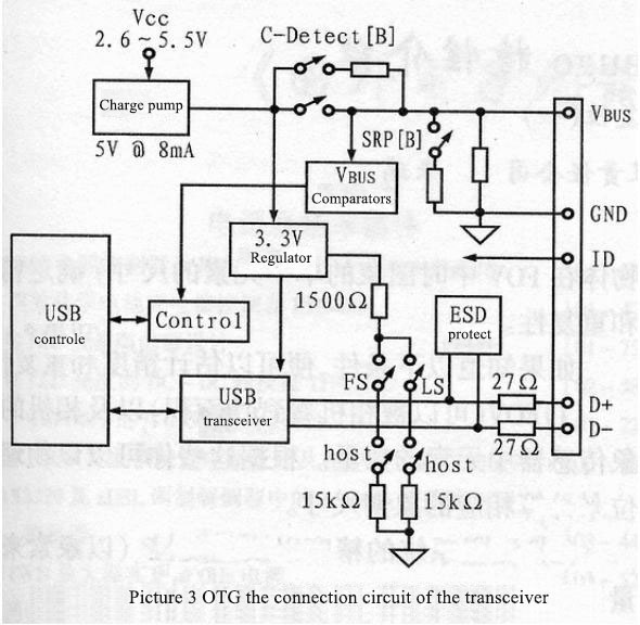
The circuit shown in Figure 3 shows the circuit that needs to be added to the basic USB peripheral when building the OTG function. The universal serial bus controller in the circuit can be a microprocessor and USB SIE (serial port engine), or it can be integrated μP/USB chip or the ASIC connected to the USB transceiver. The external devices that supply power to the bus need a 3.3V stable output supply voltage to supply power to the logic circuit and the 1500Ω resistors connected to the D+ and D- pins. Through the pull-up resistors on the D+ and D- pins, it can send signal to tell the host that the device has been connected, and indicate the operating speed of the device. A resistor pulled up to D+ indicates full speed operation, and a resistor pulled up to D- indicates low speed operation. Other endpoints (including the 15kΩ pull-down resistors of D+ and D-) are used to detect the state of the pulled up resistors. Because the USB design needs to provide hot plug function. Therefore, its ESD protection circuit is mainly used to provide protection for the D+, D- and VBUS pins.
In order to increase the dual-purpose function of OTG, the transceiver function must be expanded so that the OTG device can be used as both host and peripheral. In order to realize the function mentioned above, we need to add 15kΩ pull-down resistors at the D+ and D- terminals in the circuit shown in Figure 3 and provide power for VBUS. In addition, the transceiver also needs to meet the following three conditions:
(1) The pull-up and pull-down resistors on the D+/D- cables can be switched to provide peripheral and host functions.
(2) When used as A device, it needs to have VBUS monitor and power supply circuit. When used as a B device to initialize the SRP, it needs to monitor and trigger VBUS.
(3) Has ID input pin.
As a dual-purpose OTG device, the ASIC, DSP, or other circuits connected to the transceiver must have the function of acting as both peripheral and host, and should switch their roles according to the HNP protocol.
Most of the circuits that the transceiver needs to add are used for the management of the VBUS pins. As a host, it must be able to supply 5V power and an output current of 8mA. The analog switches in Figure 3 are used to configure the various functions of the transceiver.
The ASIC and controller must also contain USB host logic control functions, including send SOF (start-of-frame) packets, send configuration\u36755input\u36755output packets, determine transfer progress within a USB 1 msec frame, send USB reset signals, provid USB power management, etc.
The usage of OTG line function
The use of OTG is very simple, and it has something to do with the equipment, but the operations are all the same with minor differences. The operation steps are as follows:
Origin and Development
Origin
After the USB1.0 specification was released in 1996, USB-IF (Universal Serial Bus Implementers Forums) has successively announced several specifications such as USB2.0 and USB OTG. Among them, the transmission bandwidth of USB2.0 can reach 480Mbps, and USB OTG allows USB device to get rid of the limitation of the original master-slave architecture and realizes the end-to-end transmission mode. With the continuous improvement of the USB specification, the application field of USB has also been expanded. The original intention of inventing USB was to simplify the connection between computer and its peripherals. It was first applied on keyboards and mice, but now, USB application has expanded from PC peripherals to consumer electronics and communication electronics. The most significant applications are on digital cameras and other consumer electronics products. The low power consumption, easy connection and high-speed transmission characteristics of USB have made it become an easy-to-use architecture, and allows it to combine with other technologies to create new applications. For example, in the mobile storage field, the combination of USB and flash memory has created a widely popular mobile storage device – USB Drive.
Development
As shown in the statistic file from In-stat/MDR published in February this year, in the next few years, the peripheral devices with USB2.0 OTG interface will increase from 110,000 in 2002 to 168 million in 2007, an increase of 1527 times. You can see that, with the diversification of peripheral devices and the demand for high-speed transmission, the ongoing development trend of USB 2.0 OTG is very optimistic. From the perspective of industry applications, many companies have announced that they will configure USB OTG functions for their products. It is foreseeable that USB OTG will become the basic configuration function of electronic products in the future.
Leave a comment